Products & Services
Power Sections and Flex-Coupling Transmissions
Our field-proven power section designs provide the optimal combination of speed and torque delivered directly to the bit which produces unsurpassed performance. Viper has the right power section to meet the most demanding environments. Speed and torque delivered from the power section is transferred via a high strength flex-coupling transmission for maximum torque output and reliability.
Combined FLEX SHAFT / BALL JOINT design reduces area of a coupling at the rotor, taking eccentric motion of the power section & transfers power to concentric motion to bearing pack – uses best material available This is the highest rated transmission on the market.
This connection and design exceed stall torques of the new age power sections and gives the operator the comfortability to use the power section as the application demands, and not to minimize their operation due to traditional motor designs.
Top Sub / Rotor Catch
Top Sub Features a one-Piece Rotor Catch Housing, Float Bore and Top Connection all in one piece eliminating additional body connections. Rotor Catch Stems Torque directly into the top of the Rotor, and are mounted with a large cap inside the Top Sub for retrieval of the entire motors and eliminate the expensive fishing procedure of a rotor / motor.
Fixed Housings / Adjustable
Fixed Housing available in multiple angles upon request. Kick pad’s dressed with Hardened and Malleable coatings to withstand life during slides and create consistent build rates and reduce costs while operating. Adjustable Housings are available in 0 – 3-degree increments and feature saw blade type splining for ease of adjustment in the field and to ensure proper connection torque during operation.
Viper Motor Optimization Module (On board) ViberSmart
- Exclusive technology
- Sensor placed in motor top sub, motor bit box or in another BHA component.
- Memory data downloaded at surface for interpretation.
- Data reviewed with depth verses time.
Data Sets:
- Temperature
- True Motor RPM
- Axial Shock and Axial Vibration
- Radial Shock and Radial Vibration
- Motor Circulating Hours
- Torsional and Stick Slip Vibration
- Easy viewing and plotting capability for post analysis of all data sets
Viper has an extensive line of drilling motors designed for specific applications, including:
- Directional Drilling
- Coiled Tubing/Workover
- Horizontal Drilling
- Coal Bed Methane Drilling
- Performance Drilling
- HDD/River Crossing
- Coiled Tubing/Workover
- Geothermal Drilling
Short Bit to Bend Motors:
The Viper Short Bit to Bend motor reduces drilling time by completing vertical, build and lateral sections in a single trip. Designed to deliver better build rates at lower bend settings. The V-SBTB motor can be rotated during drilling without costly damages. Lower bend setting equal less stress & vibrations on the entire BHA and harmonics.
Procedures
Viper Energy Technology, in combination with Measurement While Drilling (MWD) systems and improved bit designs provide operators with an enhanced rotary drilling application. Better rates of penetration are possible when a Viper Downhole Motor is matched to the drill bit and the formation to be drilled. Because the Viper Downhole Motor will allow the operator to reduce drillstring rotary RPM, wear and tear on the casing, the drillstring and other topside components while improving wellbore penetration and drilling efficiency.
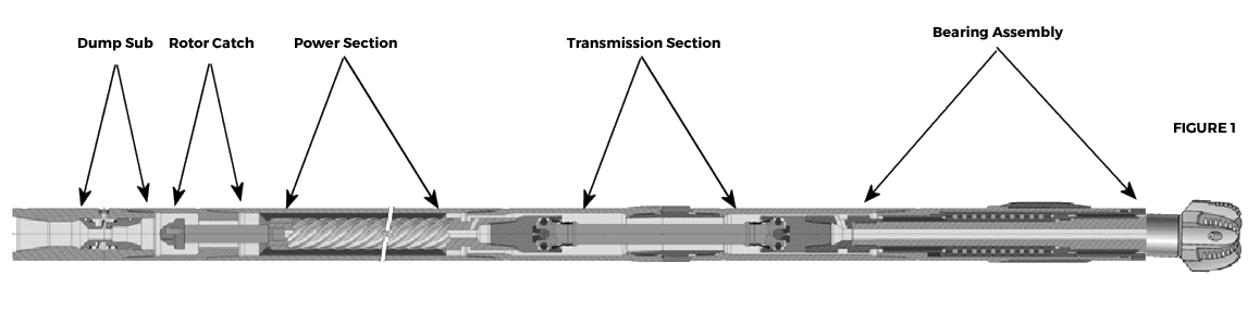
The main sub-assemblies of Viper Energy Technology are the power section, adjustable or fixed housing, driveshaft or transmission section and the bearing assembly. See Figure 1. Specialized component availability and interchangeability of the components which make up these sub-assemblies allow for customization of a Viper Downhole Motor to a particular drilling application.
Power Section
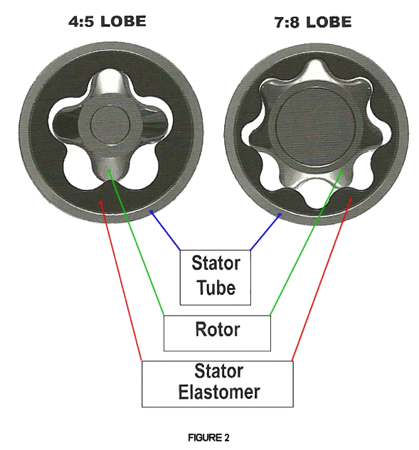
Modern drilling motors are an adaptation of a positive displacement hydraulic pump in a reversed application. It converts hydraulic power from the drilling fluid into mechanical power to turn the bit. The power section has two components. The first component is the rotor which rotates inside of a Stator tube. This is a multi-lobed helical shaped shaft that is chromed or of carbide manufacture. The second component is a stator. A stator is a steel tube filled with a highly abrasive resistant elastomer rubber, molded with one more lobe than the mating rotor. The stator is stationary while the rotor spins inside of it. The difference in the number of lobes (the stator will always have one more lobe than the rotor) causes a cavity to be formed which is sealed along the edges. As drilling fluid is passed through the power section under pressure created by the rigs mud pumps, the force turns the rotor. The rotating action created continues to open and close new cavities created by the stator and rotor combination. This action converts the hydraulic force of the drilling fluid under pressure to mechanical torque to turn the bit.
Torque and rotational speed can be varied by employing different rotor/stator lobe configurations. In general, a higher number of lobes produce increased torque and a lower number of lobes generate increased speed. Additionally, rotational speed is proportional to the circulation or flow rate for a given lobe configuration. The eccentric placement of the rotor in the stator causes the axis of the rotor to rotate about the axis of the stator. This movement acts as a gear reduction mechanism and causes bit speed to reduce as rotor/stator lobe configuration increases.
Viper Energy Technology come with power sections which offer a wide range of bit speeds and torque outputs. Additionally, power sections designed for high bottom hole temperatures are available. Figure 2 shows the relation- ship between the rotor with one less lobe than the stator tube. As stated above, the hydraulic force of the drilling fluid as it passes through the ever-changing “void” of the empty lobe generates the mechanical torque to turn the bit. Given the same flow rate for both power sections shown in Figure 2, because of the larger cavity available for the drilling fluid to pass through, the 4:5 lobe power section will turn faster making for a higher speed motor. At the same time, because the rotor is turned easier within the stator tube, the motor will generate less torque. With the reduced cavity size in the 7:8 lobe power section, the same flow rate will turn the rotor slower and generate more torque.
Fixed Housings
The Viper Performance Motor is an example of a fixed housing motor. This motor has a straight fixed housing with no bends. Motors with fixed housings set at 0° to 3° are available through special order.
Adjustable Bent Housings
Adjustable housings are available in 0° to 3° settings. The angle setting is easily field adjustable to produce a wide range of build rates. The desired bend angle can be reset on the rig floor, eliminating the need to send the motor to the shop to be changed. Procedures for changing the bend angle on the rig floor are found later in this handbook.
Transmission Section
The Viper Downhole Motor transmission section converts the eccentric motion of the rotor spinning inside of the stator tube into concentric rotation for transmission to the bearing assembly. It also delivers the torque load from the rotor that is caused by the pressure drop across the power section to the bearing assembly.
The transmission section in the Viper Downhole motor has been designed with a larger driveshaft than found in many other downhole motors. The stouter design was engineered to transfer more torque to the bit and to significantly reduce the chance of a twist-off caused by the use of the larger PDC bits with more cutters currently utilized in modern drilling projects.
Bearing Assembly
The main purpose of the bearing assembly is to allow the bearing mandrel to turn concentrically inside of the outer housing. In the bearing assembly, the torque from the power section as transferred through the transmission section is transferred to the bit. The radial bearings in the bearing assembly keep the bearing mandrel centered and running true while counteracting the forces applied to the mud motor from the bit while drilling. Thrust bearings are stacked one on top of the other to accommodate “on-bottom” drilling weights. The assembly also houses “off-bottom” thrust bearings which are used during circulating and non-drilling activities.
In sealed bearing pack motors, the bearing assembly is pressure balanced and the bearings are enclosed in an oil-filled, self-contained reservoir that is sealed to prevent contamination from the drilling fluid.
In mud-lubed bearing pack motors, the bearing assembly is also a pressure balanced system in which a percentage of the drilling fluid passes through the bearing chamber to lubricate the bearings.
Viper Energy Technology offers both sealed bearing pack and mud-lubed bearing pack motors which are designed to accommodate nearly any drilling need.
Top Sub
A top sub, or crossover sub as it is sometimes called, is used to attach the motor to the drillstring. The crossover sub typically has a standard API box connection that connects to the drill-string and a pin connection that connects to the motor. Top subs may also be designed with a float bore for those applications that may require float valve.
Rotor Catch
Viper Energy Technology are available with Rotor Catch assemblies which will assure the extraction of the rotor from the motor should there be a failure further down in the assembly. All Viper motors are delivered with a rotor catch.
Drilling Motor Applications
Operators, drilling contractors, and service and supply companies continue to strive to improve drilling technology. Since the very beginning of rotary drilling more than 100 years ago, their goal has been to reach their drilling objective in various drilling environments, quickly, efficiently, and at a reasonable cost so wells are productive and profitable. Through that time, drilling targets have become increasingly more complex and more difficult to reach. Being able to drill further, faster and longer required a method of delivering more horsepower to the bit without rotating the drillstring. Downhole mud motors which can deliver varying levels of horsepower, RPM and torque, have become the best way to accomplish that goal.
However, more than one mud motor design configuration was required to fill the needs of different drilling applications. This need has led to the design of several different types of downhole motors specifically configured to the drilling application for which they are needed. Typical applications and motors are presented in this section.
Performance Drilling (Straight-hole / Vertical drilling) Applications
A high speed drilling motor can be used for performance drilling applications. By turning the drill bit several times faster than the drill-string, a motor can effectively provide an increased rate of penetration (ROP). Since the motor is providing the rotation to the drill bit, rotational speed (RPM) of the drill-string can be significantly reduced from standard rotary drilling speeds, thus resulting in reduced drillstring wear and fatigue. The mud motor can provide angle control during adverse conditions, and aid in kickoff, and in correction and sidetracking situations.
In planning of today’s more complex wells, downhole motors offer considerable benefits as opposed to conventional rotary drilling technology, that must be taken into consideration in the cost / benefit analysis between drilling with and drilling without a motor. Some of the benefits of drilling with a motor for vertical drilling applications include:
- Reduced drilling time as a result of faster rate of penetration (ROP)
- Reduced drill-string rotational speed, resulting in less wear and fatigue on drillstring connections.
- Straighter holes resulting in faster and smoother casing setting.
- Better quality in-gauged hole
Directional Drilling Applications
Cost efficient directional and horizontal drilling requires a “steerable” system which can drill through different formations without the need to trip to change assemblies. Viper motors can be configured with either a slick assembly or with a fixed or adjustable bent housing depending upon the specifications of the drilling project.
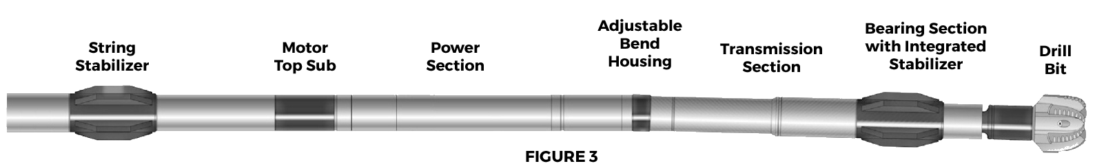
Drilling with a motor configured with either a fixed or adjustable bent housing with a stabilizer on the bearing housing and, depending upon the application, with one or more stabilizers in the drill-string above the motor effectively accomplishes this goal. Using this configuration, drilling can be accomplished in both oriented and rotary modes. Figure 3 shows an example of this type of configuration.
The advantages of this set-up include:
- A planned build rate can be adhered to using a combination of orienting and rotating.
- Drilling performance is enhanced because of the ability to deliver maximum horsepower and torque at the bit.
- The motor makes it possible to better achieve the desired bit speed which has been matched to the formation characteristics.
- Once the desired build is achieved, the assembly can be rotated as necessary to hold angle and make minor corrections to inclination and azimuth. As a result of being able to correct the wellbore course at any time.
- Torque and drag are reduced through the minimization of tortuosity
- Extended intervals can be drilled without the need to trip for assembly changes
The steerable assembly or assemblies used in a well plan application are dependent upon the desired rate of build, dogleg severity needed, and the expected rate of penetration (ROP) in both oriented and in rotary modes. The degree of bend in the motor is critical to effective management of efficient drilling.
Among the important considerations are:
- To reach the desired build rate, the expected build rate in oriented mode should be slightly higher than required. If the actual build rate is greater than required to meet the parameters of the well plan, a combination of oriented and rotary drilling can be used to make necessary adjustments.
- An assembly configured to build in rotary mode will build at a slower rate and thereby increase the length of the build-up section. Short periods of oriented drilling may be needed to ensure the average required build rate is achieved. This specific application would apply where the end of the build section coincides with a casing point, or where ROP in rotary mode is significantly more than in oriented mode.
NOTE: Rotation of the drillstring with a Viper motor set at 2° or higher is not recommended. The customer will be billed for any repairs to the motor which result from rotation of the motor set at 2° or above.
If orientation is anticipated for only short course corrections in an extended drilling interval, a smaller degree of bend in the motor will help reduce dogleg severity over the oriented sections and minimize bending stresses in the motor while rotating. However, in a long horizontal section, high frictional forces could severely reduce ROP when in the oriented mode. To insure a steady efficient ROP, a greater bend in the motor will enable oriented corrections to be made over a shorter distance. Again, rotation of a motor set at 2° or above can cause severe damage to the motor, motor failure downhole, and loss of the wellbore.
Introduction of a bent motor housing into the drill-string increases the bending stress above and below the bend. This stress is maximized when the bend is oriented opposite the hole curvature. Conversely, minimum stress occurs when the bend is aligned with the hole curvature. If the stress is above the endurance limit for the motor housing or connections, a failure will occur.
Downhole fatigue failure can be prevented if certain limitations are considered. The fatigue life / bending stress is affected by hole size, motor size, bend angle, hole curvature, toolface orientation, inclination, and stabilization, among other factors.
General recommendations which help prevent failures are:
- Drillstring rotation should be kept as low as possible. Most applications can be utilized with drillstring rotations in the range of 40-70 RPM.
- Backreaming off bottom should be done with care. The maximum bending stress for each downhole motor size is a function of the items listed above (hole size, motor size, hole curvature, motor bend angle, hole inclination, stabilization) as well as stress caused by compression from applied weight on bit and size and stiffness of the drill collars located above the motor.
- Each motor run should be evaluated individually for potential fatigue factors.
Horizontal Drilling
Horizontal drilling has become more common over the last decade. Horizontal drilling is an application of directional drilling with a steerable system, and could not be accomplished without the aid of a downhole motor. The use of a mud motor makes it possible through controlled orientation and rotating to steer the wellbore down to a horizontal depth at a desired location with a desired azimuth.
Using the motor in the horizontal section, instead of attempting to rotate the drillstring, enhances the rate of penetration due to the mechanical horsepower which the motor applies to the bit, while reducing potential failures due to fatigue or sticking. The motor is used to keep the well on course with changes made as needed in the orientation, and can be configured as necessary to provide the dogleg severity needed to reach the well plan target(s).
A wide range of power sections is available to accommodate performance in either vertical holes or extended interval horizontal drilling. By using a low angle adjustable or fixed housing motor with a stabilizer (usually ¼” underguage) on board, sliding to achieve course corrections is aided. Selecting a motor for desired torque, RPM and horsepower which is matched to the bit (PDC, diamond, or rockbit) and the formation(s) to be drilled will result in the best performance in terms of ROP and efficiency of reaching the desired target(s).
Hole Opening
The ability to drive large aggressive hole openers with a motor provides considerable flexibility when performing hole opening operations. In an opening operation, the additional cutting face requires higher torque to turn the bit/reamer. In these cases, the operator has the option of not rotating the drillstring, rotating the drillstring at a lower RPM in order to avoid damage to the casing or liner, and in many cases, rotating the drillstring only to achieve improved performance and better hole cleaning.
Hole Spudding
Offshore spudding operations can be aided by the use of a high torque, low speed drilling motor. In this instance, the drillstring can remain stationary or be used only to optimize drilling performance. The low flow rates help to minimize the possibility of bore hole wall and sea bed erosion damage. Higher flow rates required for efficient hole cleaning can be achieved when correctly nozzled jetted rotors are used. The high motor output torque allows controlled drilling operations to proceed with lower a weight on bit.
Conductor Pipe Setting, Cutting and Milling Operations
In cases where experience has shown the likelihood of problems due to hole wall collapse or string / formation contact hampering setting of conductor pipe, a motor and an underreamer may be used. An example of this type of situation are where the wellbore features a formation of high pore pressure followed by another layer with significantly lower pressure. Severe mud losses with simultaneous hole collapse are the common result. Another application would be in drilling unconsolidated sands or other unstable formations.
In these instances, drilling and the running of pipe liner are accomplished simultaneously. Although, mud losses and hole collapse may still occur, the liner is then already in place and protects the borehole. When the desired depth has been reached, the underreamer is retracted and the drilling assembly can be removed from the conductor pipe. Since there is no rotation of the drillstring in the conductor pipe, a high level of torque to the underreamer is achieved while wear to the conductor pipe is minimized. In the same manner, a motor can be used to provide high torque without high drillstring rotation for casing cutters in both vertical and highly inclined holes.
The output torque range of motors provides flexibility for milling cement plugs and milling metal in casing windows and complete casing sections.
Air and Foam Drilling
The Viper Sealed Bearing Pack downhole motor is the ideal configuration to be used when drilling with air or foam. Because the bearing pack is lubricated and sealed, the motor is not seriously affected by the lack of lubrication in the drilling media. The bearing pack is cooled by its internal lubrication. That said, careful attention should still be paid to all operating parameters in the planning and drilling operations when drilling with air, mist or foam.
Much higher volumes have to be circulated to obtain adequate hole cleaning when using these mediums because of their lower drill cutting lifting capacity. These higher flow rates must be considered when selecting the motor to use.
Because of the compressibility of air, differential operating pressures should be kept constant during drilling operations with air, foam or mist. A motor stall may not be signaled by an abrupt increase in standpipe pressure as would be the case with conventional drilling fluids since there is a time delay between actual motor fluctuations and standpipe fluctuations observed at the surface. However, an immediate loss of ROP would likely indicate a stall. Adjusting weight on bit gradually to attain the best ROP is more critical with air or foam because the motor is more sensitive to weight on bit changes than when run with conventional fluids.
When using air, foam or mist, standpipe pressure must be reduced before lifting off bottom to restart a stalled motor or when a connection is to be made. Allowing a motor to run freely off bottom may cause the motor to suffer significant internal damage. The motor may have a runaway situation where the motor RPM rises above design parameters causing severe vibration and internal damage. If air is used, it is essential that a lubricant is added to the air in order to form a mist which will provide necessary lubrication and reduce friction to the dynamic load bearing surfaces. Liquid soaps and gels mixed with fresh water are generally used and injected at rates between 7 and 11 barrels per hour.
Motor Applications Planning
Many factors go into the decision of which Viper Downhole motor would be the most advantageous to use for a particular drilling project. Many of those factors are considered during the well planning stage of the project, aided by drilling software programs and consulting the directional expertise of your Viper Technology representative.
Those considerations include:
- BHA analysis which considers individual components, component sizes and placement for directional performance while sliding or rotating.
- Torque and drag analysis of the various BHA components, including reactive torque.
- BHA stress analysis with respect to various loadings from drillstring components and projected formations.
- Hydraulic analysis taking into consideration hole cleaning and motor and bit operation as well as hole stability.
- Well path considerations to avoid collision and insure reaching the target formation or location.
- A drilling operations plan which considers contingencies, drilling economics and monitoring of actual well progress vs. proposed plan.
Once the proposed plan has been examined and understood, motor applications planning takes over. Good motor applications planning must consider all aspects of the drilling objectives, downhole parameters present, surface equipment, and downhole equipment.
Drilling Objectives Considerations
Well profile, points of interest, (formation changes, faults, dips etc.) initial inclination/azimuth, kick-off point, build rates, drop rates, tangent sections, permissible dogleg severity, intermediate inclinations / azimuths, required rates of penetration, MD’s, TVD’s, horizontal displacements, time periods for operations, final inclination/azimuth, well geometry (smooth transitions), number of bits, trips and time factors.
Downhole Parameters Considerations
Known hole problems – sloughing shales, differential sticking, string drag etc.
Hydraulics Requirements
Mud properties, flow rates and system pressures for motor operation, bit hydraulics, hole stability, hole cleaning.
Circulating Fluid Data
Chemical constituents, weights, viscosities, solids content, additives (LCM, friction reducers), formation fluids chemical constituents.
Formation Lithology
Types, dips, faults, drilling characteristics, etc.
Surface Equipment Considerations
Pump pressure and flow rate capacities. Draw works overpull capacity. Drillers console gauge reliability/accuracy – flow rate, pressure, WOB, overpull, string rotation, reactive torque. Drillpipe Filters/screens to be utilized.
Downhole Equipment Considerations
BHA component geometric and physical properties, placement and performance with respect to directional tendencies, bending stresses, shock loading, fatigue loading, vibration loading, effects on motor and survey equipment performance and data transmission.
Drill Bit Considerations
Viper Energy Technology can be run with Tri Cone, TCI and milled tooth bits, PDC and diamond bits. Viper offers specially designed drill bits with superior bit technology to meet the needs of today’s drilling projects.
When planning drilling operations with drilling motors, the same basic considerations for bit selection used in rotary drilling operations are applicable. While the formation to be drilled is a key factor for consideration, the increased RPM at the bit generated by the motor and varied WOB comparable to conventional rotary drilling applications are also factors to be considered in bit selection.
The primary objective of bit selection is to provide a cost-effective means of drilling with the desired ROP and directional control. The selection seeks a balance between minimizing hole and casing problems and maximizing bit, motor and associated tooling reliability and longevity.
Drilling rate and bit wear is determined by the interrelationship of bit, formation properties, drilling fluid type, hydraulics and mechanical drilling parameters (such as drilling motor characteristics).
Formation properties which affect bit design (geometry, material specifications etc.) should be considered with motor mechanical bit loading parameters. Formation properties include compressive strength, abrasiveness, porosity, deformational mode, permeability, stickiness, formation thickness and fracture bed types (which can affect directional control of steerable motors).
The bit cleaning and cooling effects of various drilling fluids should be considered along with the effects on motor operation or components in matching of motors and bits to specific formations. The ideal selection of drilling fluids will provide well control, conditioning and cleaning of the wellbore and minimization of wear on the motor and the bit selected.
Mechanical drilling parameters which are directly related to bit selection include motor output RPM range (which may be supplemented with drillstring rotation), WOB (which is generally less than with similar rotary applications) and vibration/shock loading.
Operating Hydraulics
Every effort has been made to design the Viper mud motor to be as compatible as possible with conventional rotary drilling practices, surface / downhole equipment and drilling fluids. A wide-selection of motors is available which can operate in water (fresh or salt), water-based mud systems, oil-based mud systems, chemical (polymer) mud systems, air and foam systems with lubricants. These circulating fluids provide a source of hydraulic energy which is converted to mechanical energy in downhole motors and MWD systems.
Additionally the drilling fluids provide cooling for downhole tool components which interact with the formation and other tool components and hole cleaning by suspending and moving solids and cuttings to the surface.
Proper hydraulics planning in the well planning process endeavors to promote motor operations efficiency while enhancing motor performance and reliability. Consideration must be given to the pressure losses in the hydraulic system which are introduced by the drilling motor.
Frictional losses in the motor power section and internal components below the power section result in fluid pressure losses. These losses must be considered along with losses from surface equipment (pumps, hoses, etc.) and the internal and annular losses from drillpipe, collars, and other BHA components. A proper hydraulics plan / review will take into account the planned motor, planned BHA components, drilling fluid, etc. to maximize the performance of the projected drilling plan and proposed drilling fluid.
The motor frictional pressure losses are minimal as the motor is run free off bottom or at the surface. Differences in power unit designs will result in differences in the free running pressure loss values between motor sizes. It should be expected that each motor will have slight differences in frictional pressure loss due to mechanical parts fitment and individual wear characteristics.
As the motor contacts the formation downhole and WOB is applied, the increased torque requirements as the bit begins to drill, the differential pressure will rise. Given a constant flow rate, an increase or decrease in WOB will result in proportional increases or decreases in torque and differential pressure. In many cases, varying the amount of WOB applies can result in optimization of ROP.
Along with varying WOB, flow rates and drill string rotation rates can be varied to accommodate formation characteristics. Since formations are rarely homogenous, output torque is not directly proportional to the WOB used. Additionally, factors such as fluid characteristics with additives aboard, temperature changes and formation fluids or gasses can affect both free running and operating differential pressures. The maximum operating differential pressure which is specified is below the maximum attainable by the motor.
Viper motors should not be run outside the specified operating ranges. The specified operating parameters for Viper motors are designed to promote efficiency and longevity of the motor. Since higher differential pressures accelerate the wearing of internal parts, motor control is reduced. Reduced motor control increases the tendency for the motor to stall or cause serious internal damage to motor components. Damage caused to motor components due to the operation of the Viper motor outside of specified operating ranges will result in additional charges to the customer for repair or replacement of those components.
Rotor Jetting
In some drilling applications, a high circulation fluid flow rate for bit and hole hydraulics may be needed. Other applications may require that the bit be rotated at a specific speed. In these cases, the high flow rates affect rotor / stator seal efficiency causing fluid leakage and increased rotor and stator wear. A motor configured with a rotor which has a machined axial bore and interchangeable jet nozzles can be utilized in these situations.
When the jet nozzle is used, the nozzle diverts excess flow from the power section. This allows sufficient pressure build-up across the rotor and stator to produce the required torque and bit rotation without excessive wear on the rotor and stator. The nozzle size should be carefully selected for the specific application.
Whether a motor has a solid rotor or is jet nozzled, a given flow rate and pressure supplies the same hydraulic energy. All of the hydraulic energy is available to drive the rotor in the case of the solid rotor. However, in the jetted rotor, some amount of pressurized flow rate is bled off through the nozzle, resulting in less pressurized fluid available to drive the rotor.
As the pressure drop across the rotor and stator varies, the fluid volume passing through the rotor jet nozzle also varies. As the motor circulates off bottom, this volume is at a minimum. It is important to select the rotor jet nozzle size so that, when circulating off bottom, the flow through the rotor / stator does not exceed the maximum recommended flow for the motor. A relatively large diameter nozzle is required under the no load (off bottom) situation since the pressure loss across the rotor and stator is low. High flow rates would then pass through the nozzle at high rotor/stator pressures. The flow through the rotor and stator under high load conditions is significantly reduced by the flow passing through the nozzle. RPM and HP are also reduced as a result. No additional pressure losses are added to the hydraulic system when using a jet nozzled rotor since the effective pressure drops across the rotor and stator and the rotor nozzle bore occur in parallel.
The minimum flow through the rotor/stator should be 2/3 the maximum recommended flow rate when a jet nozzle is used to reduce bit RPM. The jet nozzle can be replaced with a blanking plug when required flow rates are within the normal motor operating range or when the standard bit rotational speed range is acceptable.
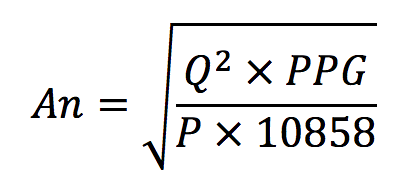
To select the correct jet nozzle size the following information is required:
- Planned operating differential pressure (P in psi) based on required output torque.
- Required flow rate to pass through the jet nozzle. This is equal to total flow rate minus required flow rate across rotor/stator (Q in gpm).
- Circulating fluid weight in pounds per gallon (PPG).
The jet nozzle area (An) may be calculated using the following formula:
Circulating Fluid Chemicals
Since the downhole motor is dependent on circulating fluid for its operation, all aspects of the circulating fluid should be considered with respect to motor efficiency and longevity. The typical types of circulating fluids are:
- Fresh and Salt water based
- Oil-based fluids
- Oil emulsion
- Polymer
- Air
- Foam
Circulating Fluid Considerations
Consideration of the type of circulating fluid to be used are related to motor wear characteristics, and potential for component damage through erosion and abrasion by solids, metallic corrosion and possible elastomer degradation by the circulating fluid or produced fluid chemicals. The fluid considerations include:
- Base waters or oils and primary chemicals and solids.
- Additive chemicals, solids and gases (e.g. nitrogen).
- Recirculated cuttings solids.
- Temperature and pressure effects.
- Fluids, gases and solids introduced from the formation.
- Gas introduced during surface operations (aeration).
Water-Based Muds
The various types of water-based mud are:
- Calcium Muds – Lime and Gypsum muds used to inhibit swelling in dispersive and reactive clays and shales.
KCI / Polymer Muds – used where there may be swelling shale and the chance of permeability damage of production zones. - Salt Saturated Muds – suitable for drilling salt domes and salt sections. Can be used with polymers to inhibit swelling of bentonite shales. Viper offers motors with carbide rotors which can be run safely in salt saturated conditions.
- Fresh Water-Based Muds – used when drilling non-reactive or compacted formations.
Native Muds – produced by pumping water downhole where it reacts with formation clays. These muds typically have high solids content and a thick filter cake. - Lignosulfonate Muds – used for muds where high drilled solids contamination exists and low filter loss is required.
In water-based muds, water is the continuous phase. To provide viscosity and suspension properties, swelling clays such as bentonite or non-swelling clays such as attapulgite (salt gel) may be added. To provide mud weight, inert solids such as barite, and marble or limestone (calcium carbonate) are added.
To control various properties such as viscosity, yield point, gel strength, fluid loss and to control corrosion various chemical additives may be added. Because of the potential for component abrasion, corrosion or elastomer degradation, the type and quantity of chemical additives, as well as the size, quantity and abrasiveness of inert solids must be considered in planning the drilling operation.
Oil-Based Muds
As a general rule, in oil-based muds, oil is the continuous phase and water is the depressed phase. These muds are commonly referred to as being “invert emulsions.” The oil phase may be highly refined mineral oils, weathered crude or diesel. The water phase may range from fresh water to nearly saturated salt water.
The primary emulsifiers in most oil based muds are a calcium / sodium / magnesium fatty acid soap. Water and treated bentonite clay provide gel strength and barite suspension properties. The soaps provide emulsion stability. In some applications, asphalt may be added to raise the viscosity and for filtration control.
One of the benefits of using oil-based muds is that they are generally more thermally stable than water-based muds. They are not as susceptible to theology fluctuations at high temperatures. However, oil-based muds may thin out when heated, resulting in a steady pressure drop as circulating fluid temperature increases.
It should be understood that chemical interactions between the motor elastomer compounds and the chemicals which make up an oil-based fluid could result in elastomer degradation. Otherwise, oil-based muds normally cause less component corrosion problems than water-based muds. Oil-based muds also provide for higher protection against bore-hole instability due to their higher lubricity than water-based muds. The result is less wear on moving components, especially bearings. There is also reduced stress on threaded connections and other components caused by tight hole, high drag, and high rotary torque, etc.
Polymer Muds
Several problems can be encountered in clay systems. Although they provide essential theological and filtration properties to circulating fluids, they may also cause high solids content, high viscosity and high gel strengths. High solids content muds often cause high pressure losses which may result in a loss of hydraulic horsepower for the bit nozzles and for the motor. High gel strengths can cause surge and wash problems.
Polymers may be added to water-based muds in order to regulate the solids content which is beneficial to maintaining a steady horsepower. The advantage of polymer systems is that they can aid in maintaining adequate viscosity and barite suspension with minimum solids content. Additionally, are generally compatible with other water-based fluids and the chemical make-up of most polymers is not sensitive to salt contamination.
Various polymer systems have been developed for specific applications. They may reduce fluid loss to permeable formations, enhance hole cleaning and increase ROP. They can be either of synthetic origin, or be from natural sources (organic / inorganic.) The chemical make-up of some polymers will allow their use downhole in temperatures in excess of 300°F.
Many polymer fluids have been chemically engineered to help reduce friction and therefore result in lower system pressure drops than found in clay-based drilling fluids. Free running motor pressures are reduced through polymer’s friction reducing properties and minimum solids content. Polymer systems should be considered for addition to water-based circulating fluids due to their positive friction reducing benefit on the rotor and stator power unit. In some cases, the use of mud lubricants or thinners can also cause reduced motor operating differential pressures.
New Mud Systems
Ester, Ether and Alternative Invert Emulsion Systems
The industry has developed new mud systems designed to be nearly biodegradable and more environmentally acceptable than conventional mineral oil-based muds. The only significant change is the replacement of the base oil with ester, ether, or another alternative fluid.
These alternative fluids do not contain any hydrocarbon aromatic compounds. Ester systems are temperature stable to 300˚F, while ether systems are used for higher temperatures. These alternative mud systems exhibit physical properties similar to those expected with conventional oil-based muds. Torque, drag, motor pressure drops, etc. react similarly. A possible drawback, however, is that some motor elastomers are not compatible with these new fluids and testing of the elastomers should be done prior to use.
Circulating Fluid Maintenance
Hydraulic inefficiencies, drillstring / BHA component problems, and formation instability may result from failure to properly institute maintenance or conditioning procedures to ensure the integrity of a circulating fluid system. The incorporation of additives into the system may be required do to changes in the mud characteristics during drilling or formation changes. Changes in temperature, formation fluids and solids and changes required due to formation changes at different depths would be common occurrences potentially requiring additional additives.
Utilization of solids control equipment and the addition of chemicals and solids at the surface are the means to the needed maintenance and conditioning. The chemicals or solid additives can potentially cause corrosion to metallic components of the motor or affect elastomer and sealing components. Fluctuations in rotor and stator friction resulting in free running and differential pressure fluctuations can be caused by the geometry and concentration of added solids. The abrasiveness of added solids may cause accelerated wear of motor components. Sand content should be maintained at less than 2% of circulating fluid during motor operations.These factors should be taken into account in the selection of the exact circulating fluid mix which will be used.
Circulating Fluid Problems
As stated above, mechanical equipment at the surface or chemicals and solids may be used to modify the circulating fluid during drilling operations to alter the characteristics of the circulating fluid. These alterations may be required by changes in the fluid due to influxes of formation solids, chemicals or gasses, fluid losses or due to adverse formation reactions and drillstring problems.
To achieve a basic understanding of the changing nature of a circulating fluid system, and the effects that contaminants of maintenance and conditioning operations may have on motor performance, some of the common circulating fluid problems are discussed. The following list details the contaminants commonly encountered in drilling fluids:
- Formation solids
- Soluble salts, including cement (e.g. sodium chloride, calcium sulfate, etc.).
- Acid gasses (e.g. hydrogen sulfide and carbon dioxide). Although these contaminants are commonly found in both water and oil-based muds, they do not normally present a serious fluid system handling problem.
Clays, shales, sands and unconsolidated formations increase solids content of the fluid due to interaction of the drillstring / BHA with the hole walls. Shales and clays may hydrate, swell and erode, especially in water-based muds, which can cause a rapid increase in mud solids content and mud viscosity.
Soluble salts act on some water-based mud solids in a manner that caused the fluid to thicken and water loss to increase. This can act with high solids content to increase potential for motor component wear.
Increased solids in drilling fluids can increase motor component wear. The problems which can result include excessive pump pressures, lost circulation of fluid, high levels of torque and drag of the drillstring, packing off, and increased fluid loss in addition to motor problems. Of special concern is sand content of the mud. Because of the highly abrasive nature of sand, high mud sand content will significantly increase motor component wear.
Soluble salt and acid gas contaminants can cause motor component corrosion and degradation. By causing a reduction in circulating pH and a tendency for the mud to trap oxygen, soluble salts increase the likelihood of motor component corrosion.
The most common sources of soluble salts are salt water flows, sub surface stringer / salt beds, anhydrite and gypsum. Caustic Soda is typically used ton increase and maintain the pH value of circulating fluids.
Cement that is thoroughly set does not normally contaminate oil or water-based circulating fluids. However unset cement contamination can cause increases in calcium and pH values. Chemical treatment and dilution are used to restore optimum properties. Additionally, cement slurries can have a high abrasive solids content which can thicken muds and accelerate wear of motor components. Efforts should be made to minimize the contamination of drilling fluids with unset cement.
Circulating Fluids at High Temperatures
Water-Based Muds (WBM)
Higher temperatures cause degradation in many additives and chemical reactions are accelerated. As a result, motor component corrosion may be accelerated and motor performance negatively affected. Elastomers in the motor also tend to degrade at a faster rate at higher temperatures.
Oil-Based Muds (OBM)
Due to their reduced potential for chemical reaction at increased temperatures, Oil-Based muds are significantly more stable than WBM. However, some chemical compounds within OBM may interact more readily with elastomer compounds in BHA components which leads to component degradation.
Lost Circulation
Remedial procedures and materials used in lost circulation circumstances may affect motor performance and longevity.
Loss of circulation to the formation results from two basic causes:
- Seepage Loss to the Formation – gravel beds, course sands, shell beds, naturally fractured formations and cavemous formations.
- Hydraulic Fracturing – caused by exceeding the fracture gradient of the exposed formation; dynamically (ECD or surge / swab pressures) or stratically (excessive mud density).
In the worst cases, the drilling assembly must be pulled and the circulating fluid conditioned or formation squeeze procedures employed. Less serious losses may be treated with the drillstring in the hole. In either case, the lost circulation materials may remain in the fluid system for some time, potentially affecting subsequent drilling assemblies. Potential for motor component corrosion or wear should be considered in choosing lost circulation materials. Chemical content, geometry, abrasiveness and concentrations have potential negative effects on motor performance and longevity.
Fibers and flakes are commonly used in low density muds for seepage and natural fracture losses. Motor operating differential pressures and output torque values may be affected by the friction reducing properties of these materials. Incorrect mixing or pumping rates can result in the plugging of motors, jet nozzles and MWD equipment.
Granular lost circulation materials are commonly used for induced losses in weighted mud systems. The same considerations apply when selecting the materials to be used. Large size hard materials tend to wear motor components and will more readily plug a motor if mixed incorrectly.
Corrosion
Corrosion resistance is an integral attribute of motor component materials and surface coatings. High grade alloys and stainless steels are used and machined to stringent specifications. Advanced surface coatings are applied to components where needed. The use of these quality materials and surface coatings generate the required mechanical properties and corrosion resistance needed for motor performance and longevity. Every effort should be made to minimize or avoid corrosive agents which may be present in or added to circulating fluids during drilling operations in the form of gases, fluids or solids.
Various agents found in circulating fluids which promote different forms of BHA component corrosion include:
- Oxygen – Oxygen is a major cause of drillpipe failure and corrosive pitting of motor components
- Carbon Dioxide – Although carbon dioxide is not as corrosive as oxygen, high concentrations can cause corrosive pitting.
- Hydrogen Sulfide – Can cause severe pitting damage, stress cracking and sudden component failure due to hydrogen embrittlement.
- Salts ( Alkali and Acid) and Organic Acids – can cause moderate to severe corrosion pitting damage (chloride attack).
During drillstring rotation operations, motor components, including housings, are subject to cyclic loading. The existence of corrosive fluids increases the potential for component wear during periods or drillstring rotation. Avoidance of corrosive agents helps to minimize the possibility of accelerated cracking, embrittlement, and other corrosive attack on statically stressed motor components.
Further, increases in downhole temperature will increase corrosion rates. Under downhole pressures, entrapped corrosive gasses may go into solution in the circulating fluid, increasing its corrosivity.
Various additives are used to reduce circulating fluid corrosivity, including:
- Oxygen and sulfide scavengers
- Inhibitor fluids and films
- pH maintenance additives
It should be noted that addition of corrosion reducing agents in the circulating fluid during drilling operations may result in motor pressure fluctuations. Some corrosion reducing additives have a corrosive effect of their own. The corrosive effect of these agents should be taken into account when planning drilling operations. For example, while caustic soda may be added to circulating fluids to maintain pH level, at certain temperatures, some caustic soda concentrations can cause serious metallic component corrosion.
Influx of acid gas into the system can occur at any time. Carbon dioxide and hydrogen sulfide reduce mud pH and greatly accelerate corrosion, especially in water-based muds. These acid gasses have the potential to cause sudden and severe motor component corrosion attack.
Additionally, when used motors are inactive at the rigsite, or during transit, high corrosion levels can occur. Draining and flushing the motor clean using non-petroleum based lubricants can reduce the potential for and severity of static corrosion of motor components.
Temperature Effects
Elastomer Component Considerations
Many elastomer components are incorporated into the mud motor, including the power unit stator, transmission unit joint covers, radial bearings and various “O” rig seals. These components have been selected to resist abrasion, erosion, circulating fluid chemicals and commonly encountered downhole temperatures. As stated previously, maintaining low levels of fluid sand and solids content in circulating fluids will aid in minimizing effects of abrasion and erosion of elastomer components. Following specifications for maximum flow rate will also reduce abrasion and erosion.
As a standard, high temperature service transmission joint covers and seals are fitted. When needed, special high temperature service stators can be supplied.
Elastomers generally can be divided into two types: non-polar and polar. Non-polar elastomers, such as natural rubbers, are susceptible to attack by non-polar hydrocarbons. These non-polar hydrocarbons are common in drilling fluid base oils. Polar elastomers, such as high grade nitniles, offer good resistance to attack by the levels of polar media typically found in oil-based drilling fluids. For this reason, polar elastomers are commonly utilized in downhole drilling tools. Polar media attack can cause elastomer swelling, swelling and reduction in strength which will significantly reduce stator longevity.
In the past, the aniline point of circulating fluids has been used to indicate the tendency for a circulating fluid to degrade elastomers. By definition, the term aniline point refers to the temperature when, under test, a specific volume of the highly polar aromatic liquid called aniline completely dissolves in a similar volume of oil sample to form a clear solution. This would be the point at which the polar circulating fluid chemicals would dissolve into motor elastomers and result in softening and swelling. Aromatics attack both polar and non-polar elastomers.
The aniline point provides an indication of the cumulative content of aromatic compounds in an oil. Generally, the lower the aniline point, the greater the tendency of an oil to cause damage to elastomer components. It is recommended that oil-based circulating fluids have as high an aniline point temperature as possible to minimize elastomer component degradation. Values of 165°F (74° C) and above are recommended. Whenever possible, the mud aniline point temperature should be above the maximum downhole operating temperature expected.
The low toxicity mud systems generally used today have much lower aromatic content levels. It is recommended that oil-based muds with significant aromatic content not be used. It is also recommended that motors be tested for elastomer compatibility under simulated downhole operating conditions prior to field operations because even some low toxicity oil-based muds may contain napthenics and paraffinics which cause some rubber degradation.
Motor Operating Temperature & Pressure Data
Viper Downhole motor components are manufactured of high grade materials to specific tolerances to ensure effective and reliable motor performance. These components exhibit specific mechanical and physical properties which are required by downhole operating conditions.
There are many parameters which can affect motor performance and longevity. Among these are the circulating fluid, operating temperature, internal operating pressure and hydraulic pressures. In determining which motor will best meet the needs of a particular project, these factors must be considered.
The elastomeric motor components are not expected to be compressible due to pressure effects alone under normal drilling operations. However, temperature and pressure combinations and changes can affect the theology of the circulating fluid, which in turn affects motor performance and the potential for component wear and motor component degradation.
Similar temperature and pressure combinations will react differently with varying circulating fluid compositions. Using an oil-based mud with the highest possible aniline point temperature is recommended to minimize the possibility of motor elastomer component degradation at Standard temperature (ST). More stringent motor operating procedures and operating differential pressures are recommended for high temperature conditions.
When running a motor into elevated temperature boreholes, periodic stops should be made to circulate. This will allow for lower temperature fluids to pass through the motor. These stops for circulation should commence prior to reaching a depth at which the downhole temperature is approximately 212° F (100° C). Period of no circulation should be kept to a minimum. Circulating continuously normally will maintain the mud system at a reduced temperature. In all cases, a temperature drop between static and circulating conditions is dependent upon the particular circulating fluids characteristics and the individual borehole.
Once a high temperature zone has been reached, the motor should be run at the minimum differential pressure required to achieve directional performance and / or acceptable ROP. Pre-planning will help alleviate many of the problems associated with adverse temperatures and their effects on the motor. Surface conditioning may be needed on low temperatures some motors may have after being stored for some period.
A modern high temperature motor will provide the same operational and input / output characteristics as a standard temperature motor but will be able to operate at a much higher temperature. The motor power unit is sized to provide reliable optimum performance in spite of the higher temperatures. In these motors, the stator elastomer mechanical and physical properties are generated by utilizing elastomer compounds which combine to offer a low thermal expansion coefficient and minimal tendency for embrittlement. Additionally, high temperature motors utilize high temperature resistant seals, “O” rings, radial bearing elastomer and lubricating oil.
Oil-based circulating fluids with the highest possible aniline point temperature should be used in high temperature motor applications, thereby minimizing the possibility of elastomer component degradation. Specific operating procedures and motor operating differential pressures are recommended for high temperature conditions.
Temperature Extended Motors
By modifying the rotor / stator geometry, it is possible for power units manufactured from the standard and high temperature elastomer types to have their temperature operating ranges extended. These geometric changes compensate for the elevated temperature effects. The modifications are made to stringent tolerances to ensure optimum stator elastomer loading. Contact your Viper Downhole motor representative for help in selection of a Viper motor which will meet the temperature parameters of your drilling project.
Motor Mechanical Loading
Viper motors are designed to operate reliably and efficiently when subjected to various surface loadings and mechanical loadings downhole. Surface loadings include WOB, torsion, rotation, overpull and jarring. Downhole mechanical loadings may result from BHA components (e.g. stabilizers and bits) interacting with the hole wall formation. Motor internal components generate loadings in the form of reactive torque and bit side loading of the driveshaft.
Static and dynamic stress analysis during motor component design aided in the development of geometries and materials selection for the best performance of Viper motors. Individual and cumulative effects of various motor loading parameters including compression, tension, torsion, bending, fatigue, internal pressure, shock and vibration loadings for both oriented and rotated drilling modes are tested.
Well planning and drilling operations should consider the effects of motor mechanical loadings on ROP, BHA directional performance and motor longevity. An analysis should be done to determine the effects of rotation rates, bit, motor, stabilizer and BHA component geometries and physical properties and their relationships to wellbore geometry in the process of planning the drilling operation.
Rotation of Drillstring / Motors
The rotation rate of the bit is increased by the combination of drillstring rotation rate and motor output rotation rate. Adjusting the rotation rate of the drillstring helps to optimize drilling operations in some applications (e.g. improving hole cleaning efficiency). As a result, the cumulative mechanical loading effects on motor components is significantly increased during drillstring rotation as opposed to sliding (non-rotating) operations.
When drillstring rotation is planned in directional wells, flex collars, with bending stiffness ratios similar to that of the motor, or special motor housings should be used in BHA’s to reduce loadings on the motor. Even with low WOB, high cyclic loadings on bent housing motors (and straight motors in aggressive doglegs) may occur.
Since the cumulative loading effects for individual motor applications vary significantly, exact values for maximum rotation rates which incorporate a safety factor cannot be defined. BHA analysis in the well planning process should take into account loading stresses from potential drillstring rotation.
Weight on Bit
In general, WOB should be maintained at the minimum value which achieves an acceptable ROP and directional performance within the specified range for a given motor application. Increasing WOB applied to a motor normally results in increased operating differential pressure and motor output torque. The interactions between the bit and formation and related downhole parameters will govern the amount of differential pressure which can be achieved and the amount of WOB which can be applied and still avoid stalling the motor.
Excessive application of WOB, especially in conjunction with drillsting rotation, will result in accelerated wear on internal motor components and could overload the driveshaft, thrust bearings, motor housings and housing connections. Serious motor damage can result from high levels of WOB applied in overgauge holes due to high motor component stress loadings.
While WOB may be low during reaming / circulating operations, drillstring rotation can still place high mechanical loadings on motors due to the physical geometries of the wellbore.
Motor Vibration Considerations
Motor vibration should be taken into consideration for both oriented mode – drillstring static and rotary mode – drillstring rotating conditions. During motor operations, there are three types of vibration present:
- Axial
- Torsional
- Transverse / Lateral
Depending upon whether in rotary mode, the drill bit, the motor and the drillstring (if rotated) can generate all three of the vibration types. Predicting which type of vibration and how serious the problem may be is difficult. Axial and torsional vibrations can combine and load magnification can occur as a result of a slip – stick motion. Drillpipe bounce and tool joint / wall contact wear can further complicate the problem.
The eccentric motion of the rotor in the stator produces vibration. The frequency of excitation is related to the ratio of rotor to stator lobe numbers multiplied by the output speed of the motor.
Motors with bent housings and stabilizers complicate vibration analysis due to the whirling motion of the motors during rotation of the drillstring. Compressive vibration analysis needs to take into account bent sub and any eccentric housing or kick pad effects on whirling motion during drillstring rotation operations.
Various external sources of vibration dampening, including losses of viscosity in the drilling fluid and radiation of acoustic waves into the formation may occur during motor operations. Severe vibrations can occur when drillstring and bit vibrations combine with motor vibrations producing resonant frequencies. When the frequency of the applied force is equal to a natural free vibration frequency of a component or assembly which occurs at a certain speed, resonance or frequency tuning exists.
Reduced drilling efficiency, reduced BHA component life and increased rate of connection failures can result from severe vibration. Exact vibration analysis is difficult due to the inability to accurately model individual BHA component wall contact points and loads, drill bit / formation interactions and vibrations from internal motor components.
Drillstring Problems
Good drilling practices will help minimize drillstring problems. There are various reasons for the occurrence of drillstring sticking, which include:
- Junk in the hole (cuttings, sloughing, shales, junk metal)
- Differential pressures
- Plastic salt flow
- Settling of barite
- Collapse of weak or unconsolidated formations
- Build-up of cutting beds
- Modifying circulating fluid theology with inhibitive fluids and solids can address wellbore instability and assist in adequate hole cleaning.
Reducing mud weight may avoid differential sticking. Additionally, elimination of lubricants, wetting agents and friction reducers which can cause fluctuations in motor operating differential pressures and output torque is recommended. Motor operation and longevity can be enhanced by careful consideration of the effects of the chemical content and mixing procedures of inhibitive fluids / solids, lubricants, wetting agents and friction reducers. Short trip cleanup cycles will also aid in hole cleaning.
Thrust Bearing Balance
The hydraulic energy of the circulating fluid acts upon internal components of the motor (power section, transmission unit, drive shaft and bearing assembly).
Due to fluid restricting/sealing effects of the internal component geometries, pressure differentials are created which result in a hydraulic thrust which is directed down through the motor’s internal components to the bit (commonly referred to as “Pump Off Force”). On large diameter motors where the rotor and flow restrictor areas are large, the magnitude of the pump open force often exceeds the anticipated WOB. In high bit pressure drop applications, the same large forces are also generated and must be taken into consideration for off-bottom loading.
The application of WOB produces a mechanical thrust which is directed from the bit up through the motor internal components. Any imbalance between the hydraulic down-thrust and mechanical upthrust is supported by the thrust bearing assembly and transmitted to the motor housings. To obtain maximum power transmission efficiency and thrust bearing life, the hydraulic downthrust loads should be balanced against the mechanical upthrust load.
Viper Energy Technology can be configured for specific drilling objectives: WOB loadings, bit characteristics, circulating fluid characteristics and formation characteristics. Bit hydraulics are considered to ensure compatibility of the hydraulic downthrust load range with the mechanical upthrust load range (WOB).
Motor Operations Procedures
Overview
Achieving the drilling objectives of the well plan in an efficient manner requires proper rigsite inspection, testing and operation of Viper motors. Consideration should be given to factors which contribute to motor component wear or damage. These include:
- Excessive operating temperature, flow rate, drillstring rotation, WOB, motor operating differential pressure, bit differential pressure and wellbore dogleg severity.
- Effects of circulating fluid chemicals and sand / solids content which may adversely affect motor components or motor performance.
Initially, Viper motors should be run at a reduced rate in order to allow components to be acclimated to the current operation and to ensure that all operating parameters are within recommended guidelines.
Motor Configuration, Inspection and Reporting
Inspection of the motor should be performed prior to operation. It is recommended that the following information be recorded:
- Motor Type / Size (check against well-plan and shipping documents)
- Motor Serial Number
- Dump Sub Fitted?
- Stabilizer Type and Size (including blade information)
- Adjustable Housing Angle
- Fixed Bend Housing Angle
- Rotor Jet Nozzle Size (if any)
- Bearing Configuration (May be painted on the motor)
Additionally:
- Visually check overall condition of motor housing, top and bit connections, bent housing / adjustable housing and stabilizer or protector sleeve.
- Lengths between Bit Box to Stabilizer, Stabilizer to Bent Housing / Adjustable Housing, Bent Housing / Adjustable Housing to connection at bottom of dump sub, connection at bottom of dump sub to top of motor.
Pre-Run Motor Surface Tests
A number of basic motor tests should be performed before operation of a Viper motor downhole in order to assess motor condition, motor performance and diagnose potential problems. If a used motor has not been run for a significant period of time after testing following a previous run and was not flushed with water / oil, it should be re-tested prior to use.
It should be noted that for correct motor operation, pressure, WOB, flow rate and drillstring RPM, the gauging on the drill rig must be accurate and the pulsation dampeners must be in good working order.
- Check the operation of the dump sub by moving the sliding piston with the aid of a wooden drift. Do not use a metallic drift.
- Make the motor up to the Kelly or rig top drive, then lift the motor free of the slips and lower it until the dump sub is below the rotary table. Avoid possibly damaging the bit by testing the motor without the bit attached. Protect the motor bit box with a thread protector during lifting operations, removing it prior to flow testing.
- Gradually raise the flow rate to the minimum specified flow rate for the particular Viper motor and record flow rate and corresponding pressure. Whenever possible, record the flow rate and the corresponding pressure at the point where the dump sub valve closes.
- Continue to raise the pump flow rate to the planned operating rate and record the flow rate and corresponding pressure. Note: The vibration and noise which can occur during testing are inherent to the motor design and not an indication of potential problems with the motor.
- With the pumps still running, raise the dump sub above the rotary table and inspect the fluid ports for leakage (clean the housing / ports) for ease of observation).
- Raise the motor to observe the bearing assembly fluid leakage over the driveshaft (5 – 8% of total flow rate is acceptable). Driveshaft rotation should not be erratic.
- Lower the dump sub below the rotary table, stop the pumps and allow the dump sub to open. This may require the opening of surface equipment bleed valve due to pressure lock.
- Raise the motor above the rotary table and check for thrust bearing gap (play).
- Radial bearing play can be checked by placing a chain tong on the bit box and applying side loading to the driveshaft. On a new motor, radial bearing float should be negligible.
- The bit is made up by locating the make-up tong on the motor bit box (rotating component) and the bit breaker on the bit.
Procedure for Setting the Adjustable Bent Housing
 Placement of the tongs on the motor requires close attention to ensure that the correct connection is un-torques and re-torqued. Should the wrong connection be un-torqued, the motor should be returned to the nearest Viper Motor Facility for repair. Make-up torque may be different from that of the adjustable bent housing.
Clearly mark the two desired number slots with paint prior to tong operations.
Adjustment of the Viper bent housing is easier with no BHA components made-up above the motor.
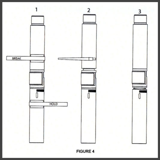
Adjustment of the Viper motor adjustable housing can be accomplished at the rigsite using the following steps as shown in Figure 4 and Figure 5:
 NOTE: All treads are RIGHT HAND.
- With the motor set in the slips, set tongs where indicated and break the connection.
- Keep the Adjusting Ring engaged to the Offset Housing with chain tong and back off the Stator Housing Adapter two turns.
- Disengage the teeth of the Adjusting Ring.
- With a chain tong, hold the Adjusting Ring stationary and with another chain tong, rotate the Offset Housing until the number slots align for the desired bend. (Note: The Offset Housing should be rotated to make-up on the inner mandrel (right hand thread). If the desired setting cannot be achieved BY HAND, back off the Offset Housing until the required number slots FIRST line up.
- Engage the teeth of the Adjusting Ring at the chosen setting. Before making up the Stator Housing Adapter, ensure that the faces of the Stator Housing Adapter, Adjusting Ring and Offset Ring are thoroughly cleaned and then doped with copper-based grease. These faces are primary seals.
- Make up the Stator Housing Adapter with a chain tong and torque to the recommended value. Tables of torque specifications can be found in the next section of this handbook.
IMPORTANT NOTE: After making up the Stator Housing Adapter with a chain tong, there should be no gap between either the Stator Housing Adapter and the Adjusting Ring and the Offset Housing. Check with a feeler gauge. If there is a gap, it is probable that the Offset Housing has been backed off one turn or more too many from the Inner Mandrel. To correct this problem, back off the Stator Housing Adapter two turns, lift the Adjusting Ring and make up the Offset Housing one turn onto the Inner Mandrel. The required number slots should again be aligned. Follow the remaining steps to complete the make-up. INCORRECT ADJUSTMENT OF THE HOUSING MAY RESULT IN A CATASTROPHIC DOWNHOLE FAILURE OR TOOL JOINT SEPARATION.
Sleeve Stabilizer Adjustment
Close attention must be given to tong placement to ensure that the correct connection is un-torqued and re-torqued. Should the wrong connection be un-torqued, refer to the nearest Viper Motor Facility
Extreme caution and good rig practice should always be exercised when handling large diameter stabilizers, especially when threading on and off the motor bearing housing.
Viper motors are equipped with externally threaded bearing housings to allow for rig site changing of stabilizers and offset pads. To install a pad or stabilizer, complete the following steps:
- Raise the motor by the lifting sub and hang the bit box in the rotary table to steady.
- Clean the exterior of the motor to remove all debris near the stabilizer thread area.
- Position the make-up tong on the thread protector, the break-out tong on the bearing housing immediately above the stabilizer upset.
- Break the thread protector loose from the bearing housing.
- Remove the tongs.
- Unthread the protector by hand or with a chain tong, if necessary.
- Remove the protector by raising the motor and sliding it down over the bit box.
- Thoroughly clean the bearing housing upset threads and the stabilizer internal threads.
- Apply thread dope to both threads.
- For small diameter tools, slide the stabilizer over the bit box and thread onto the motor by hand. For larger diameter motors, position the stabilizer over the rotary table or mouse hole and gently lower the motor onto the stabilizer. Using a chain tong, turn the motor into the stabilizer until the threads start. Ensure that the lifting sub does not unscrew. After the threads start, lift the motor slightly and continue to thread the stabilizer onto the motor.
- Position the motor with the bit box back in the rotary table.
- Place the make-up tong on the bearing housing above the stabilizer thread upset. Do not tong below the stabilizer as this is a left hand threaded component.
- Position the back-up tong on the stabilizer body or tong neck if so equipped.
- Torque stabilizer to the values in to the torque value found in the Torque Specifications table in the next section of this handbook.
- If stabilizer or pad alignment is required, shims may be installed as required between the stabilizer and bearing housing. It is important to note that these shims must be oriented as to complement the 10° angle on the stabilizer and bearing housing upset shoulders.
After drilling operations are completed, the stabilizer joint should be broken, the stabilizer removed, and the protector replaced in a similar fashion to the steps outlined above. If a pad or stabilizer is to be aligned to an adjustable housing, the adjustable housing should be set first.
Float Valves
The top sub on Viper motors is bored for a float valve. A float valve is highly recommended to avoid potential fouling of the motor.
Drillpipe Filters
It is recommended that surface drillpipe filters be utilized during motor operations in order to minimize the potential for damage to motor components from solids and foreign objects in the circulating fluid. This should include tripping in hole operations. Corrective action should be taken when appreciable solids or foreign objects are observed, particularly at the shakers.
Circulating Subs
A circulating sub can be run above Viper motors to allow the displacement of LCM, or to permit high flow rate circulation. A float valve should be run below the circulating sub.
Tripping In Hole
When tripping in hole, the traveling speed of the drillstring should be controlled to avoid contact with the BOP’s, wellheads, casing shoes, completion equipment, bridges, etc. In tight spots, run the motor at minimum flow rates with minimum drillstring rotation. Tight spots can cause significant contact forces on the periphery of the bit, requiring increased torque output levels from the motor.
It may be necessary to stop at differing depths and reciprocate the string in order to avoid creating ledges. However, caution must be exercised when rotating the drillstring because the effects of hole constraints on bent subs, bent housings, motor stabilizers and motor housing configurations can cause high-level cyclic loading of motor housings and connections.
Avoid running the bit into any settled solids or hole bottom. A short distance above any settled solids, the flow rate should be slowly raised to the planned motor operating rate and circulation established in order to remove the settled solids.
Initial Motor Operations (Off Bottom)
Once hole bottom has been reached, pick up off bottom and record pick-up / slack off weights and rotary torque values. Gradually increase to the minimum operating flow rate and record the off-bottom pressure. This reference pressure will be used in the calculation of motor operating differential pressure, and torque. Bit rotational speed can be approximated by using the performance graph for the particular motor.
During drilling operations, the off-bottom reference pressure should be checked periodically to compensate for circulating fluid theology changes, increased hole depth and any changes in flow rate.
General Motor Capabilities & Considerations
When drillstring rotation is required, the pumps should be started before string rotation. The pumps should be started before going on the hole bottom. String rotation speed SHOULD NOT be adjusted while the motor is operating on bottom.
With the motor off-bottom, start the pumps and gradually raise the flow rate to the planned operating value, then apply string rotation if required. Slowly lower the string and apply WOB. As the bit contacts the formation, the additional torque required to maintain and penetrate the formation results in increased pump pressure. Increasing WOB increases the pump pressure; decreasing WOB reduces pump pressure.
Ideally, for best results on motor run longevity, a new motor should be run at reduced operating pressures for a short period of time prior to increasing to planned operating pressures. During this initial period, ROP may be slow and erratic. The string should be lifted off bottom periodically to endure proper hole cleaning.
PDC and diamond bits should initially be fun at low bit weights, increasing weight as the job progresses, until the optimum weight is achieved. Given similar formation and operating parameters, because tri-cone bits generally have less frictional drag losses than PDC or diamond bits, operating differential pressures are also generally less.
The difference between the on-bottom and off-bottom pump pressure values is the motor operating differential pressure. The pressure differential across the motor is directly proportional to the torque output of the motor. The operating differential pressure of the motor should be kept constant to apply a constant torque at the bit. This is achieved by varying the WOB. Various parameters can affect motor operating differential pressure, including:
- Formation characteristics changes due to faults, stringers, etc.
- Circulating fluid theology changes due to fluid / solids and gas influxes and additions or temperature fluctuations.
- Bit incompatibility with the formation or bit wear / damage.
Maintaining a constant operating differential pressure below the maximum specified reduces the likelihood of orienting problems due to reactive torque fluctuations and allows greater control in avoiding motor stall. A stall occurs when more torque is required at the bit to penetrate the formation than the motor can produce. Excessive WOB is often the cause of a motor stall. Maximum differential pressure for each Viper motor type can be found on the Spec Sheets which follow in this handbook.
Motor Operations Optimization
Once the motor and bit have been run-in, a feel for the formation and reactive torque can be established. At that time, the optimum drilling rate and directional control can be established by varying the WOB, and if possible, the flow rate in small increments.
Drillstring rotation of up to 50 RPM may be used to further optimize the initial drilling rate by reducing drillstring drag and stabilizer hang-ups for more effective application of WOB. Drillstring rotation is additive to the motor driveshaft rotation for an increase in bit speed. More effective application of WOB may be possible. However, cyclic loading of motor housings, connections and internal components are increased by the effects of interaction of bent subs, bent motor housings on hole constraints.
Frequent reestablishment of drilling parameters to maintain optimum ROP and directional control are often required due to significant changes of formation characteristics due to stringers or other formation changes.
Motor Operating Differential Pressure
Motor operating differential pressure relates to the pressure drop which occurs across the rotor and stator as torque is required at the bit to drill the formation and maintain bit rotation. The operating differential pressure produced across the rotor and stator is directly proportional to the torque applied at the bit and the reactive torque which acts upon the stator.
Motor operating differential pressure increases as the torque required to drill the formation increases. The increase in reactive torque which also results may cause difficulties in directional control. Rotor and stator power units are designed to operate reliably and efficiently up to a specific maximum differential operating pressure.
Running a motor at the maximum specified differential pressure results in increased output torque levels and can yield increased ROP rates. At the same time, the higher the operating differential pressure utilized, the greater the tendency for rotor and stator wear and the greater the mechanical loading on associated components.
It may not be possible to achieve the maximum specified operating differential pressure and output torque from a particular motor due to bit and formation characteristics and resulting interactions. This does not necessarily indicate that the motor has a weak power unit. For best results, it is recommended that Viper motors be operated with the minimum differential pressure required to achieve an acceptable ROP and / or directional performance.
Motors that have been run for extended periods of time may sustain low level wear to the rotor and stator pair. This may result in reduced operating differential pressures compared to for the motor in previous operations in formations with similar flow rates and WOB values. However, while ROP and directional performance remains acceptable, the reduction in differential operating pressure does not require the motor to be replaced. Additionally, elevated downhole temperatures may cause slight changes in the stator elastomer dimensions. This may result in increased differential pressure for given operating parameters.
Any motor operating differential pressure reduction rates and operating capability changes should be monitored and taken into consideration with respect to the planned drilling objectives.
Motor Reactive Torque
As a free running Viper motor is lowered to the hole bottom and contacts the formation, WOB must be applied due to the torque required at the bit to maintain rotation and penetrate the formation. As a result, power unit differential pressure also rises. The bit rotation is to the right if the motor is viewed from above the dump sub.
The torque applied at the bit produces an equal reactive torque which acts, via the motor housing to the drillstring, in an opposite anti-clockwise or left hand direction. As the amount of torque required to turn the bit is reduced, the reactive torque (which tends to turn the drillstring to the left) is also reduced. As the torque required to turn the bit is increased, the reactive torque is also increased. Reactive torque is at a maximum during the stall condition.
Motor Stall
Motor stall occurs when the combination of torque and rpm produced by the power unit is not sufficient to effectively penetrate the formation with the drill bit. Stall may occur due to excessive application of WOB, excessive string RPM, sudden change in formation characteristics, bit wear or damage, or a combination of the above factors.
When the motor stalls, the bit, driveshaft and rotor effective lock-up and remain stationary. Penetration ceases and the circulating pressure rapidly rises due to the seals present between the rotor and stator. If not caught in time, the pump pressure rises until the seals between the rotor and stator break. This will result in the passage of highly pressurized circulating fluid between the deformed lobes of the elastomer in the stator and the lobes of the metallic rotor. The combination of mechanical loading and high pressure fluid erosion can quickly result in serious elastomer lobe damage.
If the stall occurs during rotation of the drillstring, the drillstring rotation causes the stator to be rotated over the rotor which is stationary. This increases the potential for extensive elastomer damage. This situation can occur very quickly during top drive motor drilling operations. Conscious attention must be maintained to avoid motor stall and stator rotation occurrences.
Motor stall is observed at surface by a standpipe pressure increase and zero ROP. Do not wait to observe ROP if pressure gauges indicate a motor stall situation. Should a stall situation occur, any string rotation should be immediately stopped and the string picked up off-bottom. Pressure should then be allowed to drop off. This should establish bit rotation.
The operational parameters at the time of the motor stall occurrence should be checked and modified, if necessary. Flow rate, WOB, drillstring RPM and operational differential pressure parameters, as modified if necessary, should be slowly reestablished to achieve optimum ROP and or directional performance.
It is important to note that stall differential pressure drop values will vary between different power unit designs and vary between motors of similar designs due to individual power unit internal fits and internal motor component wear characteristics. Additionally, varying circulating fluid characteristics due to introduction of additives, formation fluids / gases or fluid temperature changes can affect stall differential pressure values.
Drilling with a Jetted Rotor
The fluid volume passing through the rotor jet nozzle varies with the pressure drop across the rotor and stator. When the motor circulates off-bottom, this volume is at a minimum.
The use of a jet nozzle in a rotor does not alter the relationship between differential pressure and torque. A reduction in available energy causes a reduced motor stall pressure. The pressure at which the motor tends toward stalling is also reduced.
The bit rotation speed of a motor with a jet nozzled rotor will decrease more rapidly than that of a motor with a solid rotor as differential operating pressure increases. Due to the resulting reduced operating range, motors with jet nozzled rotors require more diligent operational control when difficult drilling conditions arise.
As a general rule, the rotor jet nozzle size should be selected such that when circulating off-bottom, the flow through the rotor / stator does not exceed the maximum recommended flow for the motor. However, since the pressure loss across the rotor and stator under a no load (off-bottom) situation is low, a relatively large diameter nozzle would be required. High flow rates would pass through the nozzle at high rotor / stator pressures. This greatly reduces the flow (along with RPM and HP) through the rotor and stator under high load conditions. The jet nozzle is sized to permit a specific amount of fluid to pass through it at a specific rotor / stator operating differential pressure as established from consideration of the projected required bit torque and rotation speed.
Since premature motor component wear can result from excessively high flow rates between the rotor and stator during off-bottom circulating, the circulation rate should be reduced prior to lifting up off-bottom.
Motor stalling with a jet nozzled rotor is not as apparent on the standpipe pressure gauge since the jet nozzle permits the passage of fluid through the rotor bore. Even though less fluid passes between the jet nozzled rotor and the stator during a stall circumstance, the stall mode is still potentially damaging to a motor. Motor stall with a jet nozzled motor is characterized by an increase in differential pressure and no ROP. To avoid excessive flow / rotation, the circulation rate should be reduced prior to lifting off-bottom after a motor stall has been observed.
Motor Field Torque Testing
The practice of motor torque testing in the field can cause serious motor component damage because the motor is forced into and held in a stall mode. The practice is not recommended for Viper motors. Consultation with Viper Motor Engineering should be done before field testing motor torque.
Tripping Out Of The Hole
Prior to tripping out of the hole, circulate the hole clean by reciprocating the drillstring to approximately 30 feet from hole bottom, picking the string up slowly and lowering at a slightly faster rate. Drillstring rotation, typically at 20-30 RPM or higher, can be applied when circulating the hole clean depending upon motor configuration and hole geometry. The well profile and known problem zones should be considered.
Should the drillstring hang-up, lower and then rotate the string a low string rotation rates. Pick up at slow speeds and reciprocate the string, if required. If it becomes necessary to pull on the drillstring, individual motor specifications and maximum motor overpull values should be considered.
Post-Run Motor Surface Tests
Ideally, complete post run surface tests should repeat the pre-run surface tests. This will permit full test result comparisons which can provide useful information regarding motor component conditions.
The pre-run surface tests can be found on page 58 of the handbook.
However, rigs often do not permit time for post-run surface tests. If a motor is picked up again for subsequent applications at the rigsite, motor surface tests must be performed.
If the motor surface test procedures are not performed, the following procedure should be performed:
- Circulating fluid should be drained from the motor by holding the motor housing stationary and rotating the driveshaft clockwise (to the right when looking down from the top of the dump sub). This can be accomplished using chain tongs or the break-out tong and bit breaker / rotary table. This operation may also permit limited assessment of rotor / stator interference and correct movement of the driveshaft in the bearing assembly. The dump sub should be flushed with fresh water and any debris removed from the fluid port filters. Water should be applied with a hose attached to the box connection and permitted for flow from the bearing assembly (over the driveshaft.) Clean hydraulic oil should be flushed through the motor to inhibit any adverse chemical reactions to motor components during motor storage and transportation. DO NOT use petroleum based oil. Manually check the operation of the dump sub by moving the sliding piston with the aid of a wooden drift (do not use a metal drift.)
- A correct size thread protector in good condition should have thread dope applied and be fitted to the motor bit box to protect the connection threads and shoulder face. A lifting sub should have thread dope applied and be made up to the motor inlet (top) connection.
Motor Operations Data Reporting
To facilitate effective appraisal of motor operations, to provide a database of information for subsequent well planning and motor design development, and to aid in drilling problem analysis, it is essential that comprehensive motor performance reports are completed. Your Viper representative will discuss motor reporting with you.